Pulled this out of the archive for new site
Facebook Fabric Networking Deconstructed
Facebook engineering has recently introduced their next-generation data center network architecture planned to be operational in the new Altoona facility. Introducing data center fabric, the next-generation Facebook data center network
In this post we are going to look at the design proposed and break down some of the reasons why this design was necessary although maybe still not ideal.
Facebook, the killer app.. literally
Within Facebook’s data center the network is a critical component driving this social networks ever increasing appetite to connect people together. The challenges unfold on two axis, the first being the explosive growth in the user population and its increasing demand and access bolstered by modern mobile devices and the second related to the exponential growth of machine to machine traffic required to aggregate and compose information which we all know and love. Due to the nature of Facebook applications, machine to machine communications is “several orders of magnitude larger than what goes out the Internet”
The need to parallelize work becomes a daunting task in this environment requiring an enormous communication fabric for internal processing.
the rate of our machine-to-machine traffic growth remains exponential, and the volume has been doubling at an interval of less than a year.
Most companies never experience the level of complexity Facebook deals with on a daily basis. The ever growing “connectedness” of the social fabric brings with it huge challenges. Since the information used to compose ones Facebook page is dictated by the set of friends and the frequency of updates, Facebook must deal with complex power law distributions as hot trending topics fire off millions of requests and updates across their servers to get the latest status which can drive the network to its breaking point.
Facebook’s challenges are extreme but not completely orthogonal to previous work in designing supercomputers which require low-latency parallel connectivity.
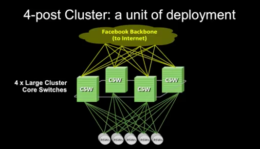
Facebook’s Four Post Architecture
The previous architecture leveraged a “3+1” cluster switch configuration in a layer 3 design used to add redundancy while taking advantage of the internal capacity of large cluster switches..
“A cluster is a large unit of deployment, involving hundreds of server cabinets with top of rack (TOR) switches aggregated on a set of large, high-radix cluster switches”
Design limitations with this approach
- Only a few vendors with capable high-radix designs
- Switch radix becomes a limit to the number of cluster attached hosts
- Switches internal capacity become a limit to advancing to higher interface speeds
- The complexity of the architectures and different design characteristics add a level of operational uncertainty.
The whole concept of a “cluster” was born from a networking limitation – it was dictated by a need to position a large amount of compute resources (server racks) within an area of high network performance supported by the internal capacity of the large cluster switches
This design should be very familiar, it is called an “augmented collapsed backbone” design in which the communications backplane is consolidated onto the internal fabric of a large radix switch called a cross-bar
“Additionally, the need for so many ports in a box is orthogonal to the desire to provide the highest bandwidth infrastructure possible.”
As long as the capacity of the switch provides enough bandwidth to match the load and there are appropriate resources such as buffers available, a high-radix switch would be ideal at delivering the highest bandwidth.
It might be better to say:
The need for so many ports in a box is orthogonal to the desired outcome related to efficiency, power and cost when maximizing for the highest bandwidth infrastructure possible since the design complexity and cost become gating factors.
Core to the design limitation of the 4-Post architecture stems from the use of a two-layer network. Lets examine this a bit further by analyzing the design constraints to a similar network, the 2-Layer Fat-Tree.
In 1985 Charles E. Leiserson publishes a paper entitled “Fat-Trees: Universal Networks for Hardware-Efficient Supercomputing”. This paper helped provide a model by which the number of components in a communication system (channels/ports) could be decoupled from the quantity of processing elements.
Fat-Trees: A family of general-pupose interconnection strategies which effectively utilize any given amount of hardware resources devoted to communication.
Other names used for Fat-Trees include : Folded Clos, Leaf/Spine, n-Layer Fat-Tree, GFT, and k-ary, n-tree (a more formalized model).
Investigating the limits of two-tier Fat-Tree
As the name suggests, a two-layer Fat-Tree is divided into two stages: The spine stage which is used to aggregate and route packets towards the final destination and the “leaf” stage which is used to connect end-hosts and load balance connections across the spine. In most modern designs Valiant Load Balancing as implemented in ECMP is used to provide randomized load balancing although with the advent of OpenFlow implementations other intereting techniques can be used.
We won’t go into all of the pathologies related to optimzing traffic here but there is an enourmous quantity of research on this topic.
Lets model a network with the following variables:
Let $P$ = The number of external ports (i.e. host attachments)
Let $R$ = The radix of the switch (i.e. how many ports are available on a single switch)
Let $L$ = The number of layers in the network ( in a two-layer design this number is always 2)
We also need to define the term min-cut
The min-cut is the minimum amount of cuts necessary to divide the network into two equal partitions. The min-cut represents the biectional bandwidth available (in other words the bottleneck throughput) and becomes an important element in designing a non-blocking fabric. We will use the terms min-cut and bisectional interchangeably except where noted.
Note: in these calculations we are using fixed radix switches (i.e. all switches have the same number of ports). All caclulations are based on maximizing bi-sectional bandwidth and such have an oversubscription of 1.
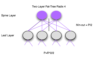
Lets use the figure above and walk through the calculations.
We will start off by designing our network to handle 8 hosts.
Let $P = TotalHosts = 8$
$$TotalHosts = R * (R^{L-1}/2)$$
Solving for $R$ we get $R = 4$.
Now that we have $R$, we can solve for the other unknowns
| Equation | Result |
|---|---|
| $TotalCores = R^{L-1}/2$ | 2 |
| $TotalSwitches = (2L -1) * (R/2)^{L-1}$ | 6 |
| $TotalPorts = R * TotalSwitches$ | 24 |
The min-cut of this network would be $P/2$ or 4 the over subscription rate can be calculated as $(P/2)/mincut = 1$ or non-blocking
$$P = {R^2}/2$$
So is R really a limitation?
Even though we can use larger and larger switches in this mathematical model, the scaling issues center around packaging constraints, power requirements and sensitivity to temperature. All data centers are constrained by power, space and cooling and therefore one must make a tradeoff between the size and allocation of power, space and cooling between processors and the communication fabric. This limit corresponds to Number 2 of our design limitations.
Practical Example Using Broadcom Trident 2
The Broadcom Trident 2 provides a total of 2.6Tbps of bandwidth and 1.28Tb forwarding performance. Lets design a network that can exploit the 32 QSFP+ ports to build a high-radix network.
Note: We will use a fixed-switch configuration normalized to 10GE interfaces.
Let R = 128
| Equation | Result |
|---|---|
| $TotalCores = R^{L-1}/2$ | 64 |
| $TotalSwitches = (2L -1) * (R/2)^{L-1}$ | 192 |
| $TotalPorts = R * TotalSwitches$ | 24,576 |
| $TotalHosts = R * R^{L-1}/2$ | 8,192 |
So with the radix limited to 128 we can only support 8,192 hosts with a Bisection of 122.8Tbps
Lets now take a look at the new Facebook Network Fabric model to see how they can scale to the upper limit of the physical capacity of a data center.
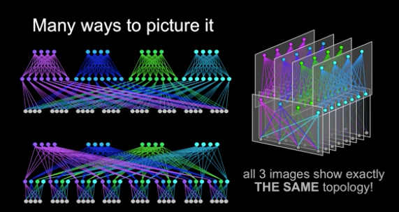
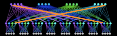
Facebook Network Fabric is a 3-layer Folded Clos Network
When looking at the image below.. even though its just a model of a much larger network design, you should recognize the symmetry and tree structure. In fact this design, even though pictured in different ways uses the same mathematical model we used above for 2-layer Fat-Trees. This is because the new Facebook Network Fabric is in fact a Fat-Tree with 3-levels.
What else do we know?
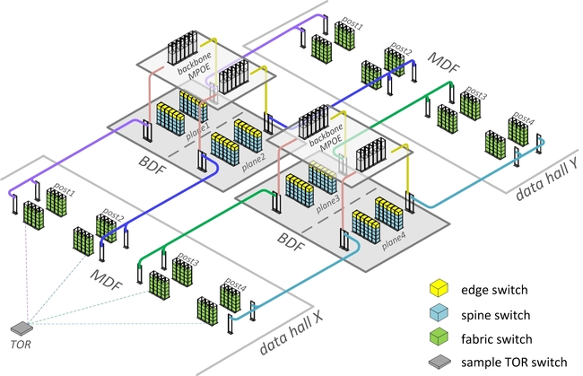
- The spine and fabric switches will operate at 40GE but be upgradeable
- The spine will consist of 4 spine planes with up to 48 nodes per plane for a total of 192 Spine switches
- All wiring will be pre-deployed to scale from a 4:1 oversubscribed network to a 1:1 fully non-blocking
- A POD will consist of up to 48 ToR switches with 4 uplinks to the fabric switches corresponding to each spine plane.
- Edge POD’s connect to the spine and are used to egress the fabric and support a capacity of 7.68Tbps
- Each TOR currently has 4 x 40G uplinks, 160Gbps total bandwidth for a rack of 10GE connected servers. The way Facebook divides the capacity across their racks is unknown.
- Each POD has 48 server racks, so a POD has 160G*48 or 7.6Tbps total capacity.
Given this we want to know:
- How many spine (core) switches will this topology scale to?
- How many fabric switches are required to achieve 1:1 non-blocking fabric?
- How many server Pods can we scale to?
- How many hosts are supported in this new network fabric?
We can use this diagram and our equations to validate we are indeed working with a network derived from a Fat-Tree
First lets just model the information we have to see if it indeed compares to our equations.
Let R = 8
| Equation | Result |
|---|---|
| $TotalCores = R^{L-1}/2$ | 16 |
| $TotalSwitches = (2L -1) * (R/2)^{L-1}$ | 80 |
| $TotalPorts = R * TotalSwitches$ | 640 |
These numbers do correspond to the graphic so we can feel comfortable that we can work out all the details based on the information provided by Facebook.

Based on the information we gathered above we can calculate all the unknowns.
Solving for R we know that the Radix of the switch being used here must be 96 (i.e. fabric switches are 48 up and 48 down).
| Component | Equation | Result |
|---|---|---|
| Total number of Spine switches | $48 * 4$ | 192 |
| Total Fabric Switches | $(2(R/2)^{L-1}) /12$ | 384 |
| Total ToR Switches | $2 * (R/2)^{L - 1}$ | 4,608 |
| Total Switches | $Spine + Fabric + ToR$ | 5,184 |
| Total Ports | $Total Switches * 96$ | 497,664 |
| External 40GE Ports | $R * (R/2)^{L-1}$$ | 221,184 |
| External 10GE Ports | $R * (R/2)^{L-1} * 4$ | 884,736 |
Gathered this information from the blog post
Here is the altered visual showing the upper limit on this design.
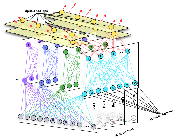
As you can see we have allocated infrastructure for 95 out of 96 server Pods, we reserve those ports exatcly 192 off the spine for our 7.6Tbps uplinks.
Note we have not included these edge ports in our calculations
So where does Facebook get a 96 port 40GE switch when the highest density fixed-function 40GE switch is around 32ports not 96?
A Cisco NX-9508 can support up to 288 40GE interfaces with a 30Tbps backplane but it is modular not a fixed function commodity switch. Facebook engineering must have something else in mind for this deployment.
Remember the Altoona data center will go live with a 4:1 oversubscription. This can be implemented with a Broadcom BCM56850 with support for up to 32 x 40GE with 2.56Tbps throughput and 1.28Tbps of forwarding capacity.
By gradually adding spine switches and upgrading to higher-radix switches Facebook can move from the current 4:1 oversubscription, to 2:1 and 1:1 the maximum allocation of ports as described above.. Stay tuned to see what they come up with.
Before we wrap this up we should talk about the dirty little problem when building these tree networks. Because of the structure of this network, Fat-Tree designs require a substantial amount of long cable runs which extend from one side of the data center to the other.
Facebook has designed the datacenter to minimize these lengths as much as possible with a uniform wiring plant which allows for a wire once run anywhere deployment.
This blog post took me quite a while to put together so I hope you find it useful.